We’re focused on making the tooling experience even smoother that’s why we’ve deployed an update to the site that adds scribe line detection to parts.
Scribe lines are impressions machined into mold tools such as curves, cross-hairs or letters and numbers. These impressions leave a resin mark on the component when it comes out of the mold.
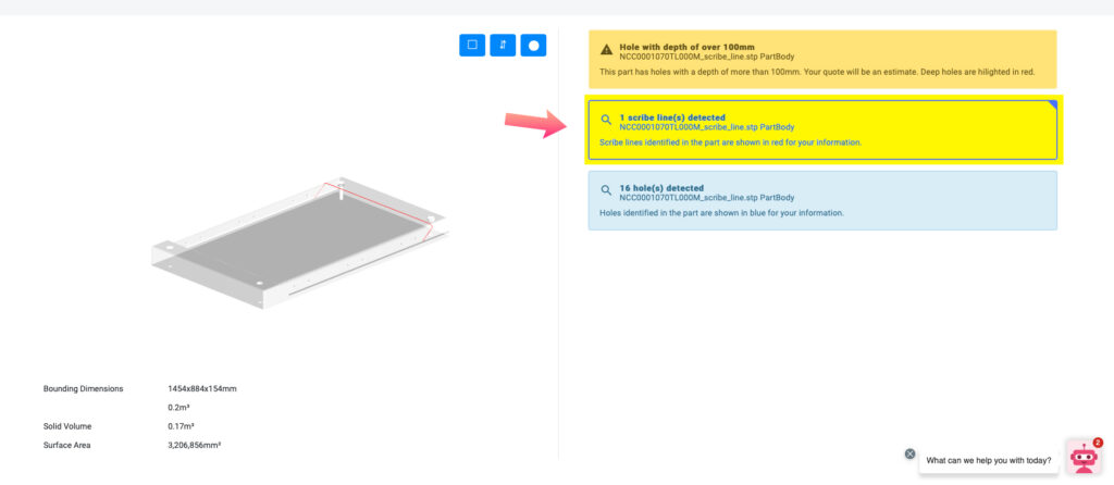
In CAD, a scribe line is represented by a composite curve which lies on the surface of the mold. Plyable will automatically detect scribe lines on your uploaded geometry and they will be displayed on your quote.
If there are scribe lines found for a part, they can be viewed by the user on the DFM page, similar to how we display holes.
More Info on Scribe Lines:
Scribe lines around the part boundary
- Precise tolerances on part edges are important, e.g. when fitting a part together in an assembly. Tight tolerances can be hard to achieve when laminating to the mold edge.
- In processes using a single sided tool with a vacuum bag consolidation can be better at the edge of the part. This can lead to uneven thickness in the final component.
- These issues can be solved by laminating past the part edge and then trimming back the excess material to the part boundary. This trimming can be done manually or using a CNC mill.
Scribe lines for holes
- For parts with holes or other features machined after the molding process, scribe lines are often used on the mold to identify these features on the final part. Circles or crosshairs are used to identify holes.
Scribe lines for numbering
- Scribe lines with a part number can be used for easy identification of the part.
Scribe lines for instruction
- Scribe lines can be used to leave instructions on the final part for example marking left and right handed parts.
Machining of scribes
- Scribe lines are machined using a tool path along the line. Plyable has a CFRP specification and GPR specification to ensure the line will leave a visible mark on the part.